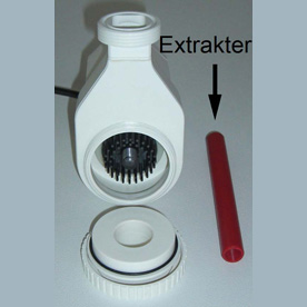
Those that are running the new style protein skimmers will have noticed that a red threaded rod has been included when unpacking the protein skimmer.
The rod has been provided as a convenient way to remove the impeller as it is of a completely new design.Please find below maintenance instructions taken directly from the product manual and pictures that will help visualise impeller removal.
Maintenance
The Deltec protein skimmer range should need very little adjustment and maintenance once set correctly
however due to the high levels of calcium in marine aquariums it is common for deposits to build up on
moving parts requiring periodical cleaning. Deltec pumps are fitted with little flaps inside the outlet of the
pump and inside the housing, which flip from one side to the other depending on the direction of rotation
thus ensuring that the pump always operates at full duty. It is recommended every 6 months, or when
required, that the pumps are removed from the skimmer having first drained the body of Water.
Check and clean the impellor of debris. Ensure that the direction flaps move easily and if necessary soak
the neck of the pump housing in white vinegar or lime scale remover to dissolve any calcium carbonate
deposits. A build up of calcium, dust and salt can restrict or block the venturi inlet on the connecting pipe
work and reduce the skimming efficiency. This should be checked and carefully cleaned with a toothpick
or fine drill rotated between the fingertips.
It is advisable to stop the pump for approximately 15 minutes once every week in order to dissolve any
dust or salt crystals that may have collected in the venturi tube.
Service hints
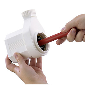
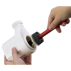
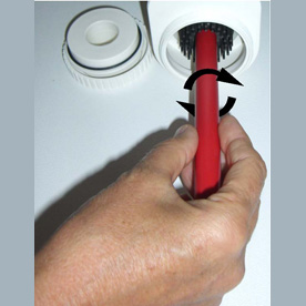
The protein skimmer pump is fitted with a very powerful rotor magnet. To remove the rotor from the pump use
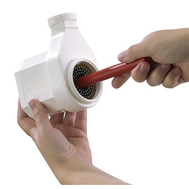
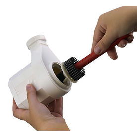
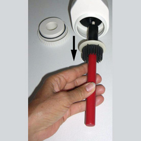
only the special extractor tool (picture 1). Screw the extractor onto the rotor’s centre piece (picture 2) and
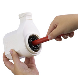
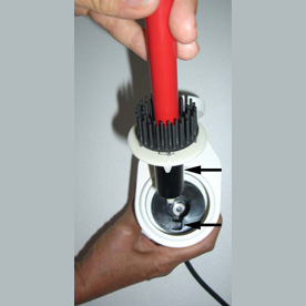
pull the rotor out of the pumps housing slowly and deliberately in a straight line (picture 3). Be careful not
to put any side forces onto the ceramic rotor shaft as this might break the hard and brittle material.
Use the same tool when inserting the rotor into the pump housing.
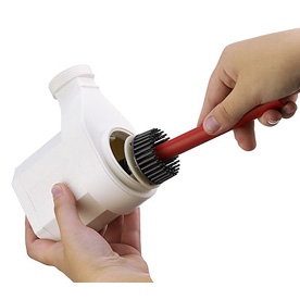
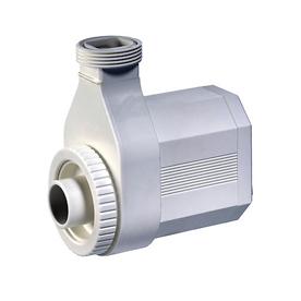
Make sure that the guide fitted to the bearing plate is located in the slot of the stator (picture 4). The
Impeller is fixed inside the stator by an o-ring. It requires a certain pressure to push the impeller the last
2-3mm into its correct position
Picture 1 Picture 2
Picture 3 Picture 4
Additional pictures