WHAT IS TDS
Total Dissolved Solids (TDS) are the total amount of inorganic elements, including minerals, salts or metals dissolved in water, other than the pure water molecules (H20) and suspended solids.
A TDS meter works by measuring the total amount of mobile charged ions dissolved in a given volume of water, expressed in total quantity as parts per million (ppm), or in weight as mg/liter. TDS is directly related to the purity of water and the quality of water purification systems. TDS affects everything that consumes, lives in, or uses water, whether organic or inorganic, for better or for worse.
For people, a lower TDS level in drinking water is typically preferred. Reverse Osmosis (RO) systems work by filtering the tap water and rejecting the waste water. You can determine your system's effectiveness by calculating the percent rejection rate.
HOW TO CALCULATE PERCENT REJECTION
(Tap TDS - RO TDS) / (Tap TDS) x 100 = Percent Rejection Example: Tap TDS = 352 ppm and RO TDS = 18 ppm. Percent rejection = 94.9%.
Contact the manufacturer of your system to determine minimum percent rejection levels and when to change the filter or membrane.
Please contact the manufacturer of your water system for recommended
TDS levels.
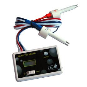
Measures the TDS levels of two different water lines such as the feed water to your reverse osmosis unit and the filtered water at any time.
The DM-1 is an ideal monitor to know if a filter cartridge, resin cartridge or membrane is functioning effectively.
Install the DM-1 so you'll always know how a water filtration or purifica-tion system is performing.
PARTS DM-1: Base Unit (LCD Display) 2 x 1/4" T-fittings (standard) 2 x 1.5V Batteries (pre-installed) TDS Range: 0-9990 ppm Resolution: 0-999:1 ppm 1000-9990: 10 ppm (indicated by a blinldng 5E10 Mon) Accuracy: 01-2% Conversion Factor: Nadi (avg. of 0.5) Factory Calibration: 342 ppm NaCI Sensor Cable Length: 24.5" (32.2 cm) (including sensor) Power Source: 2 x 1.5V batteries (model 357A) Auto Shut-Off: After 10 minutes Battery Life: Approximately 2 years Base Unit Dimensions: 3 x 0.8 01.9 in (7.8 0 2 x 4.7 cm) Base Unit Weight: 2.8 oz (79.4 g) (including batteries)
CARE AND MAINTENANCE
Very little care is necessary for your DM-1
• Never touch the sensor pins, as skin oils may adversely affect the TDS measurement.
• To clean the sensor pins, clean with rubbing alcohol and let air dry.
• Avoid removing the fittings, as doing this often may strip the plastic off the sensor and potentially cause a leak.
• If you notice the readings are off from what they should be, replace the batteries or re-calibrate.
Frequently Asked Questions (FAQs)
1. What should the TDS readings be? For drinking water and fitter performance, the lower the TDS level, the better. There is never a "right" or "wrong" number. For filter performance, calculate the percent rejection to determine performance levels. Contact the manufacturer of your filter system for recommended levels.
2. My TDS levels fluctuate. Is this normal? Yes. Slight fluctuations are normal from day-to-day. A variety of factors affect the reading.
3. Does the DM-1 have an alarm or programmable set point? No. You will need to view the readings.
4. How will I know when the batteries need to be replaced? If the display fades, the monitor does not power on, or the readings are incorrect, you may need to change the batteries.
5. Can I use the DM-1 to monitor a water softener? No. Water softeners do not remove TDS.
6. Where can I get more information on water quality? Visit www.theaquariumsolution.com
INSTRUCTIONS
The DM-1 can be configured in a variety of ways, depending upon your needs. Typically, the IN line (line 1) is connected to the source (tap) water, and the OUT line (line 2) is connected to the product (filtered) water.
The DM-1 can also be configured with multiple systems. such as an RO/DI combination.
Installation
To install the DM-1 to a water purification or filtration system:
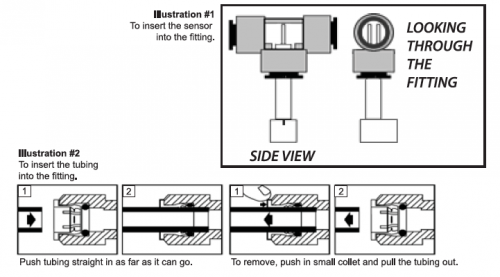
1. Insert the white sensors fully into the bottom of the T-fittings.
2. Orient the sensor pins so that they are perpendicular to the direction of the T. The water should flow over both pins equally. you should be able to see both pins of you look through the fitting.) See illustration 1 below.
3. Disconnect the water source.
4. Snip the source (tap) water tube at a point between the source and the filter. Insert both ends of the tube into the top of the IN line sensor's T-fitting. See illustration #2.
5. Snip the product (filtered) water tube at a point between the filter and a dispenser. Insert both ends of the tube into the top of the OUT line sensor's T-fitting. See illustration #2.
6. The DM-1 monitor can be attached anywhere on or near the water system using the Velcro tape. Most commonly, the monitor is attached to the water filter system.
7. Reconnect the water source. Your monitor is now ready for use.
NOTE: Consult a professional plumber for specific installation questions.
USAGE
1. Press the POWER button.
2. To display the TDS level of the feed (tap) water, slide the switch to the IN side. To display the TDS level of the product (filtered) water, slide the switch to the OUT side.
3. The displayed TDS will be most accurate after approximately 10 seconds.
4. Determining filter effectiveness depends on your particular system. For en RO system, for example, compare the IN water TDS levels with the OUT water TDS.
5. If the x10 icon appears, this means the TDS level is above 999 ppm. Therefore, multiply the reading by 10. For example, if the display shows 143 ppm with the ' x10 ' icon, the actual TDS level is 1430 ppm. (If the ' x10 ' icon does not appear, the reading on the display is the actual TDS level.
For most drinking water, you will not see the ' x10 ' icon. 6. Tum off the unit. It will automatically shut off after 10 minutes. CALIBRATION Your monitor was factory calibrated to 342 ppm. This level is suitable for most tap water/filtered water applications, so it is ready to use out of the box. However, you may need to re-calibrate based on your needs, as well as from time-to-time to ensure best results.
To calibrate:
1. Purchase a certified calibration solution that is correct for your needs. The calibration solution should be NaCI. 342 ppm NaCI is recommended.
2. Disconnect both T-fittings from their tubes. Do got remove the sensor from the T! Ensure the orientation of the sensor to the fitting is correct, as in illustration #1. Shake any water out.
3. For better accuracy, calibrate to a flowing solution. If this is not possible, you can calibrate to a still solution. Turn on the monitor and place one 7-fitting (with the sensors in it) into the calibration solution. You will get a reading. Ensure the fitting is completely filled with solution and there are no air bubbles. This step is critical for proper calibration.
4. If the reading on the monitor (for the sensor in the solution) does not match the solution, adjust the reading up or down by gently tuming the plastic orange screw on the rear of the unit clockwise or counterclockwise to raise or lower the reading.
5. There is one calibration screw to calibrate both the IN and OUT sensors simultaneously. You only need to calibrate one sensor, and it does not matter which. 6.If calibrating to a still (not flowing) solution, calibrate to 3% above the level of the calibration solution. This will accomodate for the lack of flowing water, which the monitor is programmed for. For example, if the calibration solution is 342 ppm, adjust the screws until it reads 352 ppm. If you are calibrating to a flowing solution, calibrate to the level of the solution.
6. Your monitor is now calibrated. There is no need to do anything else.
TROUBLESHOOTING
"E r r" display (error) = 1. The water is out of the monitor's range.. The sensor cable is loose or unplugged. Push the cable connector securely Into the monitor.
Incorrect readings = 1. Re-calibrate the monitor. 2. Change the batteries.
Faded display = 1. Change the batteries.
The OUT reading is higher than the IN reading = 1. Check your connections. The sensors may be reversed.